. . . the making of XC FS racing machine - STEREO . . .
The fixture consists of three 100x50x5mm steel U-profiles, which are welded together. Each part that holds any of the tubes is made of a 10mm steel plate and two small steel blocks (connected via bolts and pins) to keep the plate in place. Two M8 bolts hold each of the steel plates and let them slide inside the U-profiles.
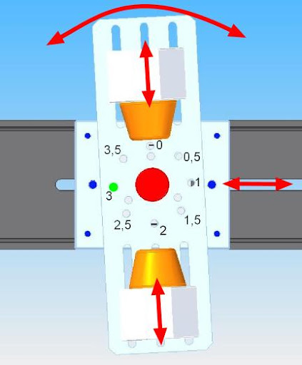
This part holds the head tube. The orange cones can be adjusted to fit different length tubes. The head angle is changed by inserting the green pin into the correct hole (8 different settings). And the whole thing can be moved to the length of the top tube.
 This part holds the upper end of the seat tube. The orange cone goes into the seat tube and the whole thing can be adjusted to fit different seat tube lengths.
 This part holds the bottom bracket. The bottom bracket slides on to the threaded axle and the orange cones are then screwd to tight fit. Again the whole thing can be adjusted to fit the correct bottom bracket height.
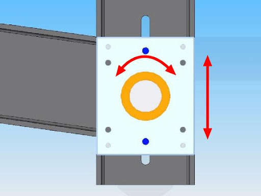
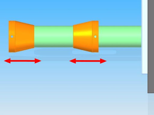 This is the holder for the rear axle. It can be adjusted to the correct chain stay length and if necessary slightly moved sideways.
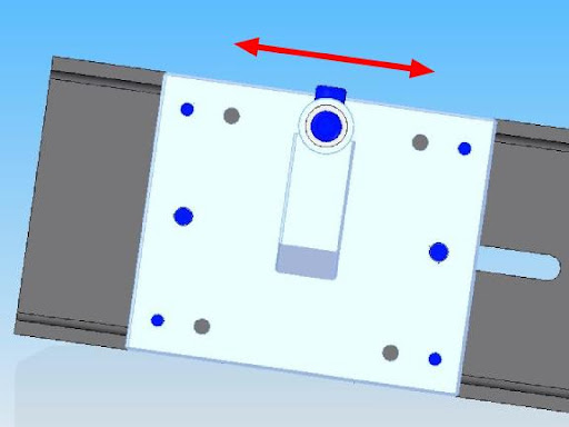
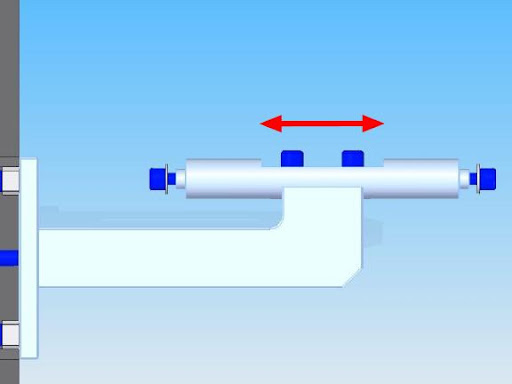
This part holds the head tube. The orange cones can be adjusted to fit different length tubes. The head angle is changed by inserting the green pin into the correct hole (8 different settings). And the whole thing can be moved to the length of the top tube.
 This part holds the upper end of the seat tube. The orange cone goes into the seat tube and the whole thing can be adjusted to fit different seat tube lengths.
 This part holds the bottom bracket. The bottom bracket slides on to the threaded axle and the orange cones are then screwd to tight fit. Again the whole thing can be adjusted to fit the correct bottom bracket height.
 This is the holder for the rear axle. It can be adjusted to the correct chain stay length and if necessary slightly moved sideways.


0 Responses to “FRAME FIXTURE part 3”
Leave a Reply